-40%
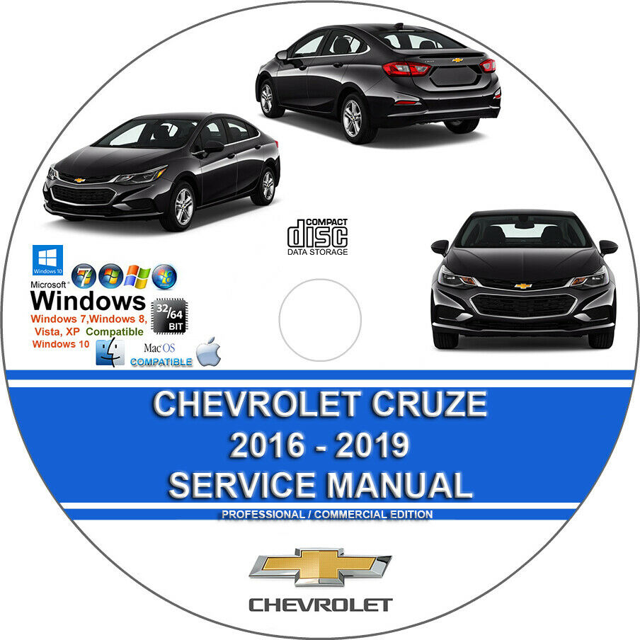
Chevrolet Cruze 2016 2017 2018 2019 Service Repair Manual on CD
$ 13.2
- Description
- Size Guide
Description
Chevrolet Cruze 2016 - 2019 Service Repair Manual on CDLoaded with illustrations, instructions, photos, and diagrams, complete to service and repair your Chevy. Read and print pages directly from the CD, or copy the entire manual to your hard drive.
11 900 Pages
We are USA seller
3 Days FREE shipping in USA.
Sorry, no Download! We send only CD out!
MODEL YEAR:
2016 2017 2018
ENGINE:
1.4L
1.6L
MANUAL COVERS:
General Information
Antilock Brake System
Automatic Transmission - 6T35 (MNU) - Component Locator
Automatic Transmission - 6T35 (MNU) - Description and Operation
Automatic Transmission - 6T35 (MNU) - Diagnostic Information and Procedures
Automatic Transmission - 6T35 (MNU) - Repair Instructions
Automatic Transmission - 6T35 (MNU) - Schematic and Routing Diagrams
Automatic Transmission - 6T35 (MNU) - Special Tools and Equipment
Automatic Transmission - 6T35 (MNU) - Specifications
Automatic Transmission - 9T50 (M3D) - Component Locator
Automatic Transmission - 9T50 (M3D) - Description and Operation
Automatic Transmission - 9T50 (M3D) - Diagnostic Information and Procedures
Automatic Transmission - 9T50 (M3D) - Repair Instructions
Automatic Transmission - 9T50 (M3D) - Schematic and Routing Diagrams
Automatic Transmission - 9T50 (M3D) - Special Tools and Equipment
Automatic Transmission - 9T50 (M3D) - Specifications
Bolted Exterior Body Panels and Closures
Bumpers and Fascias
Cellular, Entertainment, and Navigation
Instrument Panel/Center Console Component Views
Clutch
Collision Repair
Component Connector And Inline Harness Connector End Views
Component Connector End Views Wiring Systems
Door Component Views Wiring Systems
Wiring Systems Ground Views
Cruise Control
Dangers, Warnings, and Cautions
Data Communications
Wiring Systems Diagnostic Information and Procedures
Disc Brakes
Displays and Gauges
ANTILOCK BRAKE SYSTEM - DTC
Wiring Systems Component Locator - Electrical Center Identification Views
Wiring Systems Front of Vehicle/Engine Compartment Component Views
Engine Controls and Fuel - 1.4L (LE2) - Description and Operation
Engine Controls and Fuel - 1.4L (LE2) - Diagnostic Information and Procedures
Engine Controls and Fuel - 1.4L (LE2) - Repair Instructions
Engine Controls and Fuel - 1.4L (LE2) - Schematic and Routing Diagrams
Engine Controls and Fuel - 1.4L (LE2) - Special Tools and Equipment
Engine Controls and Fuel - 1.4L (LE2) - Specifications
Engine Controls and Fuel - 1.6L (LH7) Diesel - Description and Operation
Engine Controls and Fuel - 1.6L (LH7) Diesel - Diagnostic Information and Procedures
CRANKSHAFT POSITION - CAMSHAFT POSITION NOT PLAUSIBLE
DTC P0407, P0408, P046E, OR P046F: EXHAUST GAS RECIRCULATION COOLER COOLANT INLET TEMPERATURE SENSOR
REDUCTANT QUALITY SENSOR CIRCUIT
Engine Controls and Fuel - 1.6L (LH7) Diesel - Repair Instructions
CRANKSHAFT POSITION RELUCTOR RING LEARN
EMISSION REDUCTION FLUID SYSTEM DESCRIPTION
Engine Controls and Fuel - 1.6L (LH7) Diesel - Schematic and Routing Diagrams
ENGINE CONTROLS WIRING SCHEMATICS
Engine Controls and Fuel - 1.6L (LH7) Diesel - Special Tools and Equipment
Engine Controls and Fuel - 1.6L (LH7) Diesel - Specifications
Engine Heating and Cooling
Engine Mechanical - 1.4L (LE2) - Component Locator
Cylinder Head and Components
Drive Belt Accessory Components
Engine Block and Components
Engine Front Cover and Components
Turbocharger and Components
Water Pump and Components
Intake Manifold and Components
Oil Pan and Components
Timing Chain and Components
Engine Identification Code
Engine Mechanical - 1.4L (LE2) - Description and Operation
Positive Crankcase Ventilation System
Cutaway View Of Lubrication System
Engine Mechanical - 1.4L (LE2) - Diagnostic Information and Procedures
ENGINE OIL PRESSURE
Engine Mechanical - 1.4L (LE2) - Repair Instructions
Draining Fluids and Oil Filter
CRANKSHAFT BALANCER REMOVAL
AUTOMATIC TRANSMISSION FLEX PLATE REMOVAL
ENGINE FLYWHEEL REMOVAL
TURBOCHARGER REMOVAL
ENGINE OIL COOLER REMOVAL
WATER PUMP REMOVAL
THROTTLE BODY ASSEMBLY REMOVAL
INTAKE MANIFOLD REMOVAL
FUEL PUMP REMOVAL
ENGINE LIFT AND SIGHT SHIELD BRACKET REMOVAL
WATER OUTLET REMOVAL
VACUUM PUMP REMOVAL
IGNITION COIL REMOVAL
FUEL RAIL AND INJECTORS REMOVAL
CAMSHAFT COVER REMOVAL
OIL PAN REMOVAL
ENGINE FRONT COVER REMOVAL
CAMSHAFT TIMING CHAIN REMOVAL
INTAKE AND EXHAUST CAMSHAFT, BEARING CAP, AND LASH ADJUSTER REMOVAL
Camshaft Bearings and Camshaft Removal
Valve Rocker Arm and Lash Adjuster Removal
CYLINDER HEAD REMOVAL
OIL PUMP DRIVE CHAIN AND OIL PUMP REMOVAL
Oil Pump Drive Chain and Crankshaft Sprocket Removal
Oil Pump Assembly Removal
CRANKSHAFT OIL DEFLECTOR REMOVAL
LOWER CRANKCASE REMOVAL
PISTON, CONNECTING ROD, AND BEARING REMOVAL
CRANKSHAFT AND BEARING REMOVAL
CYLINDER HEAD DISASSEMBLE
Intake and Exhaust Valve Removal
Cylinder Head Oil Gallery Plugs, Turbocharger Studs, Spark Plugs, and Engine Oil Manifold Check Valve Removal
CYLINDER HEAD CLEANING AND INSPECTION
Cylinder Head and Gasket Surface Cleaning and Inspection
Valve Measurement and Reconditioning Overview
CAMSHAFT TIMING CHAIN AND SPROCKET CLEANING AND INSPECTION
DRIVE BELT REPLACEMENT
ENGINE SIGHT SHIELD REPLACEMENT
CAMSHAFT COVER REPLACEMENT
CAMSHAFT POSITION ACTUATOR REPLACEMENT
EXHAUST CAMSHAFT REPLACEMENT
INTAKE CAMSHAFT REPLACEMENT
CAMSHAFT TIMING CHAIN REPLACEMENT
Engine Mechanical - 1.4L (LE2) - Schematic and Routing Diagrams
Engine Mechanical - 1.4L (LE2) - Special Tools and Equipment
VALVE STEM OIL SEAL AND VALVE SPRING REPLACEMENT
Valve Stem Oil Seal Replacement Procedure
CHARGE AIR BYPASS REGULATOR SOLENOID VALVE VACUUM TUBE REMOVAL
Engine Mechanical - 1.4L (LE2) - Specifications
Engine Mechanical - 1.6L (LH7) Diesel
Exhaust
Exterior Trim
Floor Coverings and Headlinings
Frame and Underbody
FRONT FLOOR PANEL CARPET REPLACEMENT
Air Conditioning Evaporator and Blower Module Drain Hose Replacement
DRIVETRAIN AND FRONT SUSPENSION CRADLE REPLACEMENT
Front Suspension
HVAC Heating, Ventilation, and Air Conditioning
Horns
Hydraulic Brakes
Immobilizer
IMMOBILIZER WIRING SCHEMATICS
Inline Harness Connector End Views
Instrument Panel and Console Trim
Interior Trim and Paneling
Lighting
Maintenance and Lubrication
REMINDER INDICATOR (RESET PROCEDURES)
Manual Transmission - M32 (MF3 MZ4)
Master Electrical Component List
Mirrors
Mode 6 - GMLAN
Object Detection and Pedestrian Protection
Paint and Coatings
Park Brake
Plastic Panel Information and Repair
Power Outlets
110V AC Power Outlet (KI4)
CIGAR LIGHTER/POWER OUTLET WIRING SCHEMATICS
Mobile Device Wireless Charger Description and Operation
Power Seats
Power Steering
Component Locator - Powertrain Component Views
Programming and Setup
Luggage Compartment/Rear of Vehicle Component Views
Rear Suspension
Remote Functions
REMOTE FUNCTION WIRING SCHEMATICS
Keyless Entry - Passive (ATH) and Passive Start (BTM)
Control Module References
Passenger Compartment / Roof Component
Seat Belts
Seat Hardware, Trim, and Upholstery
Seat Heating and Cooling
Secondary and Configurable Customer Controls
STEERING WHEEL SECONDARY/CONFIGURABLE CONTROL WIRING SCHEMATICS
Generator And Starter Cable
Shift Lock Control
SHIFT LOCK CONTROL WIRING SCHEMATICS
PARK LOCK SOLENOID CONTROL CIRCUIT
Automatic Transmission Shift Lock Control Description and Operation
COMMON SPECIFICATIONS & PROCEDURES
Squeaks and Rattles
STARTING AND CHARGING WIRING SCHEMATICS
12 V Starting and Charging
Steering Wheel and Column
STEERING WHEEL WIRING SCHEMATICS
Steering Wheel and Column Description and Operation
Sunroof
Supplemental Inflatable Restraints
Module Power, Ground, MIL, Indicators, and Passenger Presence
Side Impact Sensors, and Roof Rail, Driver, and Passenger Air Bags
Suspension General Diagnosis
Theft Deterrent
THEFT DETERRENT SYSTEM WIRING SCHEMATICS
Tire Pressure Monitoring
Tires and Wheels
Transmission Cooling
TRANSMISSION FLUID COOLER FLOW TEST AND FLUSHING
View Of Main Power Switch & Main Function Switch
Trouble Shooting - Basic Procedures
Vehicle Access
DOOR LOCK/INDICATOR WIRING SCHEMATICS
RELEASE SYSTEMS WIRING SCHEMATICS
PASSENGER/DRIVER EXTERIOR DOOR HANDLE SWITCH CIRCUIT
LEFT/RIGHT REAR DOOR HANDLE SWITCH CIRCUIT
INTERIOR TRUNK LID UNLATCH SWITCH CIRCUIT
Proactive Alerts Description and Operation
Vehicle Diagnostic Information
K20 Engine Control Module: Scan Tool Information
Wheels/Vehicle Underbody Component Views
Vibration Diagnosis and Correction
Waterleaks - WATERLEAK TEST PREPARATION
Wheel Alignment
WHEEL ALIGNMENT SPECIFICATIONS
Wheel Drive Shafts
Air/Wind Noise
Wipers and Washers
Wiring Systems and Power Management - Description and Operation
Wiring Systems and Power Management - Diagnostic Information and Procedures
Wiring Systems and Power Management - Repair Instructions
Wiring Systems and Power Management - Schematic and Routing Diagrams
Wiring Systems and Power Management - Special Tools and Equipment
Wiring Systems and Power Management - Specifications
SYSTEM WIRING DIAGRAMS
This manual is the same as the manual used by workshops. Service Manual contains detailed instructions and step by step diagrams for all workshop procedures.
Language: English
Format: PDF
COMPATIBLE WITH ALL WINDOWS & MAC COMPUTERS
(WINDOWS 10, WINDOWS 8, WINDOWS 7, VISTA 32 and 64, XP, ME, 98, NT, 2000 ETC.)
Windows/Mac/Tablet/Phone Friendly
32 / 64 bit
This listing does not violate any ebay policy or copyright policy. Because of the GNU/GPL we are allowed to list this manual.
This is either on the public domain, copyright free and/or has resale rights owned by us.
This doesnt infringe the ebay rules/policy, copyrights or trademarks.
The listing including the description has been created by me based on the manuals.
The listing doesnt violate any ebay rules,copyright policy, or trademarks. It is either in the public domain, copyright free, or we have resale rights.
This Maunal doesnt have connection with autodata products. Some of its content is distributed freely under the terms of the GNU Public License and GNU Lesser General Public License.
It can be freeware freely distributing. According to the EU Laws reported in July 2002 N1400/2002 Article 4, car makers must give to independent garages and other interested persons access
to repair information. Selling workshops, Technical Repair, Technical Specification informatio, Catalog for parts and diagnostic data for vehicles doesnt constitute any kind of infringement rights.
It isnt property of software corporations or car making companies.We or our Agents/suppliers hold all copyright and/or IP rights for these products,we therefore have full and legal rights to distribute/sell them.
